

 SkillClick
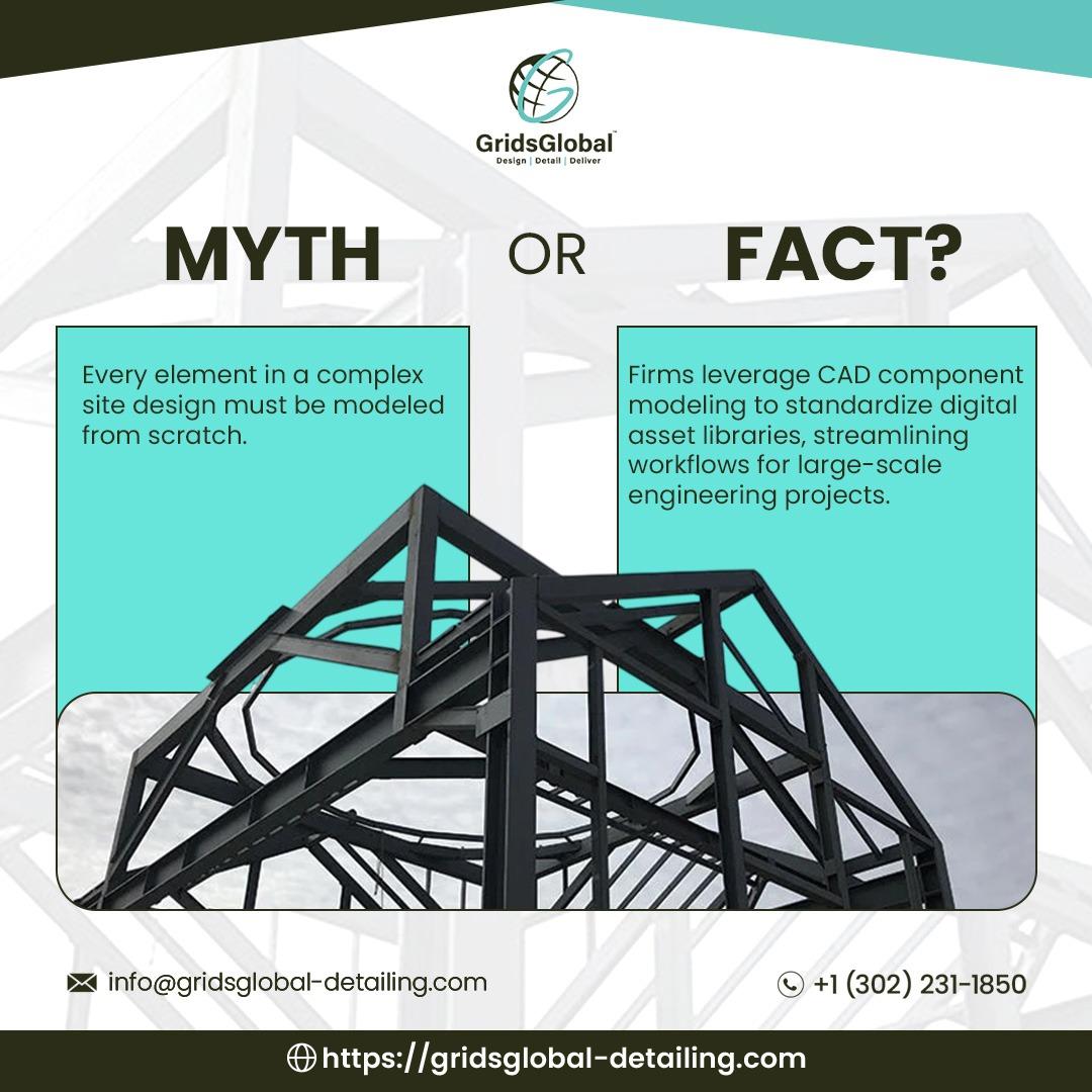
Every connection detail begins life at a comfortable room temperature. It is drawn in an office, cut in a shop, bolted on site in whatever season the schedule permits, and then asked to perform for decades of weather it never encountered on paper. That gap between the drawing environment and the service environment is where thermal movement lives, and closing it is a core responsibility of Structural Steel Connection Design Services. Their work assigns each bit of seasonal travel to a specific joint, describes the hardware in terms a shop can fabricate, and fixes the arrangement in a model so no one downstream has to guess.
What a Frame Does When It Cannot Move
Restraint is invisible in a calculation and expensive in the field. Steel denied movement does not dissipate the resulting stress, it stores it, cycle after cycle, and the stored load migrates toward whichever element in the load path has the least capacity remaining. The destinations tend to repeat: a weld root buried inside a brace, a bolt hole crowding a plate edge, a section that steps down without a taper to soften the change. Failure reports describe familiar mechanisms, including block shear tearing a gusset, prying that peels an end plate, and fatigue initiating along a fillet weld under cyclic reversal. Every one of those conditions has a check in the AISC provisions. None of those checks knows anything about restraint that never appeared on a drawing.
Getting to a Number Everyone Can Use
Thermal movement reduces to one expression: Δ = αLΔT, where α is the coefficient of thermal expansion, L is member length, and ΔT is the temperature change the member actually experiences. Steel's α is approximately 0.0000065 per degree Fahrenheit, or roughly 1.17 × 10⁻⁵ per degree Celsius. A short member moves by thousandths of an inch. A frame several hundred feet long under a wide seasonal swing moves by inches, and inches have to be accommodated deliberately rather than absorbed by luck.
Sequence decides whether the result is usable. The building designer fixes the design temperature range and the overall length first. Only then does the figure become a fact rather than a spread of possibilities. With that number settled, the connection engineer can decide which joints accept the travel, and the detailer can attach that decision to a coordinate in an LOD 400 model. Reverse the order, pick details first and trust the movement to fit, and slots come up short while bearings carry loads they were never meant to resist.
Three Conditions That Quietly Rewrite the Result
A length-only calculation captures the headline figure and misses the complications that decide whether a chosen detail actually performs.
Temperature gradient. The sunlit face and the shaded face of a deep member never equalize. That difference bends the member rather than simply extending it, which moves bearing surfaces and can bind a connection detailed for pure translation. Members exposed on one side deserve closer scrutiny than plain arithmetic suggests.
Erection temperature. Steel bolted on a cool morning carries a different built-in length than the same steel bolted at midday, and every later movement is measured from that starting point. Logging ambient temperature at erection, and erecting near the middle of the annual range where scheduling allows, divides the available travel between summer and winter instead of spending it in one direction.
Slip-plane condition. Paint, galvanizing buildup, weld spatter, or grit inside a slot or across a faying surface will defeat travel the drawings promised. AISC 360 requires washers over oversized and slotted holes, Table J3.3 governs minimum edge distance, and the RCSC Specification controls surface preparation wherever slip-critical behavior matters. None of those rules helps if the faying surface arrives on site contaminated.
Four Release Details and What Each One Actually Delivers
Connection engineers draw from a short menu of established options. Each carries a boundary worth stating plainly, because a release that cannot deliver the calculated travel is worse than none at all.
Slotted holes give a bolt a defined distance to move before it bears on the plate. Available travel equals slot length minus bolt diameter, which is modest, and bolts can bear against the slot edge or work it open across repeated cycles. AISC 360 Section J3.3 restricts oversized holes and short- or long-slotted holes parallel to the line of force to slip-critical connections. Slots therefore serve erection tolerance and small movements rather than large thermal excursions.
Sliding bearings allow one member to translate across another over a low-friction interface. AISC guidance identifies the slip-surface bearing as the most common practical method for accommodating significant differential movement, provided the surface stays clean and friction stays low.
Pins transmit axial and shear force while permitting rotation, though they concentrate force at a single location.
Double column lines create two adjacent structures that move independently. This is the most dependable release and also the most expensive.
Every option takes something in return. A slot trims net section. A bearing relocates the load path. A pin concentrates force at one point. Slip-critical strength is adjusted by a hole factor that runs 1.00 for standard holes and short slots perpendicular to the load, 0.85 for oversized holes and short slots parallel to it, and 0.70 for long slots. Inside the detailing model, each mechanism becomes geometry, a bolt schedule, and a clearance envelope the drawings can state without ambiguity. Welding symbols stay on shop work, field bolting carries the release, and gauge lines, edge distances, and hole spacing are dimensioned so the crew reads rather than reasons. Hole orientation and slot direction are called out as well, which keeps bolts installed correctly the first time.
Expansion Joints: Placement Judgment and Spacing Benchmarks
An expansion joint collects movement at a location chosen deliberately. They appear in long buildings, parking structures, and buildings with uneven exposure, such as a shaded core beside a sunlit perimeter. AISC 360 Chapter L addresses design for serviceability, with Section L6 covering thermal expansion and contraction and Section L7 covering connection slip. It requires thermal effects to be considered but does not prescribe joint spacing or location. Those calls rest with the building designer.
Published guidance supplies reasonable starting points. AISC's Steelwise article on expansion joints, drawing on Federal Construction Council Technical Report No. 65, notes that a continuously heated and air-conditioned steel building with a symmetric rectangular frame and a 50°F to 70°F design range can often tolerate about 600 feet between joints. That baseline adjusts to real conditions: an unheated building reduces the allowable length by 33 percent, fixed column bases reduce it by 13 percent, and substantially greater stiffness at one end reduces it by 25 percent. Commonly cited federal recommendations are more conservative, at roughly 400 feet for heated buildings and 300 feet for unheated ones. Joints belong where differential movement is likely, such as at a building addition, where different materials meet, or at a change in geometry like the reentrant corner of an L-, U-, or T-shaped plan.
Placement and detailing carry equal weight. The gap must absorb the full calculated travel without closing, exclude water, and allow movement along every axis the structure can take. Connection design on either side is intentional: one side is anchored, the other slides, and the erection drawings must make that distinction unmistakable before the pick. Detailing teams also reconcile joint locations against architectural drawings so the structural break aligns with facade and roofing joints, and they confirm that cover plates and flashing permit the travel the frame needs. Column bases at a joint often call for slotted base plate holes with plate washers over the anchor rods so the base itself can translate.
Who Carries the Design Responsibility
AISC 360 governs how a connection is designed. AISC 303 defines shop drawing content and the review sequence before fabrication. AWS D1.1 covers welding. The RCSC Specification covers high-strength bolts and requires slip-critical connections for joints with oversized holes and for joints with slotted holes whose slot is not perpendicular to the load, unless slip is itself the intended behavior.
Both AISC 360 and AISC 303 identify who may design a connection. The Code of Standard Practice gives the engineer of record three routes: design the connections directly, authorize a detailer to select and complete them from the contract documents, or delegate design to a licensed engineer retained by the fabricator. Section B3.1 of AISC 360 assigns responsibility to whichever party the contract documents name. On a delegated project, the fabricator's engineer designs to AISC 360 Chapter J, seals the calculations, and issues AISC 303 shop drawings that return to the engineer of record for approval.
Market conditions make this practical rather than academic. Fabricated steel demand across the United States keeps climbing, led by data centers and heavy industrial work, while detailing capacity and skilled welding labor have not kept pace. Resolving movement and fit inside the model now costs less than resolving them at the site. Texas remains home to a dense concentration of detailing firms, and delegated packages increasingly arrive with engineer seals valid across multiple states.
Problems that surface when movement is ignored are catalogued in Structural Steel Connection Design Services. Projects in seismic zones carry additional obligations under Structural Steel Connection Design Services, although seismic demand and thermal demand are treated as separate conditions.
From Sealed Strategy to Shop Packet
Detailing converts the release strategy into instructions a shop can build from. Slots appear in the model with correct travel and orientation. Bearings carry material and clearance specifications. Expansion joints are drawn at the proper width in the proper location. The detailer builds an LOD 400 model placing every cope, weld preparation, and bolt hole at its true position, then runs clash detection against ductwork, cable trays, and fire suppression lines. Constructability review follows, confirming that what has been drawn can actually be fabricated and erected. The same model supports quantity extraction, which feeds takeoffs and procurement planning.
Small details decide whether a joint assembles cleanly, and the drawings must carry them: anchor bolt templates, grout holes in base plates, shear tab thickness, cope radii, weld access holes, camber and sweep notes, and the specified finish on faying surfaces. On the fabrication side, the approved package generates cut lists, bolt lists, CNC files, and the BOM and BOQ data used for purchasing and costing. Erection drawings add sequence notes and load-in order so material ships in the sequence the crane will need it. Weld procedure specifications, welder qualification records, and mill test reports travel with the package, giving inspection a known baseline to work against. The full workflow is outlined in Structural Steel Detailing Services, with scope details under Structural Steel Detailing Services.
The Envelope Follows the Same Calendar
Movement does not stop at the steel line. Facades, roofing, cladding, and mechanical systems expand and contract on the same schedule. The structural joint must align with joints in the building envelope, and cross-discipline coordination is what prevents cracked finishes, leaking roofs, and equipment binding against its supports.
Field Notes for USA Project Teams
Bring thermal movement into the design conversation early. Fix the temperature range and the building length. Set expansion joints at intervals that suit the structure, treating published guidance as a starting point rather than a rule. Size connections at those joints for the calculated travel. Confirm that slots, bearings, and joints survive detailing and fabrication within tolerance. Check coordination with other trades before the shop cuts steel.
Regional conditions shift the numbers. Texas summer heat drives substantial growth across large facilities, which is why teams handling Structural Steel Detailing Services in texas follow expansion joint spacing and sliding connection design closely on long-span industrial and data center work. The same reasoning holds across the hotter parts of the southern and southwestern United States.
Closing Perspective
Not every project needs a thermal strategy, but those that do find their connection requirements reshaped by it. Anyone working on long-span, exposed, or parking structures should understand how a joint absorbs travel without surrendering capacity. Get that right and the frame performs through every season without complaint. Early agreement among the connection engineer, the steel detailer, and the building designer keeps movement paths clear and fabrication schedules intact.
To discuss connection design for thermal movement, constructability review, BOM compilation, and BOQ structuring for your next project, visit our contact us page.
Corporate Contact Information
United States Operations
GRIDSGLOBAL STEEL DETAILING LLC
Address: 1207 Delaware Ave, Unit 2877, Wilmington, DE 19806
Phone: +1 (302) 231-1850
Email: info@gridsglobal-detailing.com
Website: https://gridsglobal-detailing.com/